RMIM Designer Documentation (2010 Update)
| Overview | 2010/11 Updates | VocabMIF | DataTypeReleases | BatchProcess | CommandLine | Errors/Install | Vis2002-3-7-10-13 |
Introduction · SetConductionStyle · ContextBlockCodeSets · UpdateVocabRepresentations · ScanAndRepair · AlignMasterGUIDs · DualDataLoad
Introduction
This tab documents a set of important changes made in 2010 and 2011 that do not handily fall into other documentation categories.
Designating Context Conduction Style
During 2010, HL7 reviewed and completely restructured the methodology by which a serialized static model designates whether important context data applied to one element of the model also applies to "children" (in the serial hierarchical sense) of that element.
This change in context conduction control - deprecation the prior "conduction-indicator-based" method and adoption of a new "vocabulary-based" method - created the requirement to be able to designate for each model which of the methods it uses, or whether it uses neither. It was further determined that this designation would be documented as a "property" of the Entry Point for that model in its RMIM designs.
The designation is made by asserting one of three code values:
- "C" designates the model uses the original conduction-indicator-based method of establishing context conduction, a method that was deprecated during 2010.
- "V" designates the model uses the new vocabulary-based method of establishing context conduction as adopted during 2010.
- "I" designates that the model does not explicitly establish context conduction. This designation is formally "discouraged."
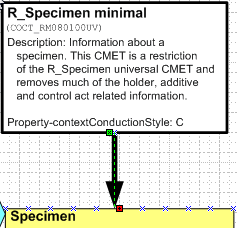
The figure at right shows the property asserted in the description of the Entry Point for CMET COCT_RM080100UV. The syntax is identical tho that used for asserting RIM properties in the descriptive text for attributes, etc. It is the Reserved fragment "Property-" followed by the property name "contextConductionStyle" followed by a colon and then the code "C"
Your Toolsmith does NOT recommend that you edit these by hand! (Except perhaps to delete one.)
Visio RMIM Designer Tool Support
Beginning with Release 4.6.6, the RMIM Designer initiates the following process whenever a static model is saved or validated:
- Determine whether the contextConductionStyle property has been set to a valid code (V,C,I);
- If set, determine whether the designation is "I" and the RMIM Designer option "Reject Inferred (I) Context Conduction Style" has been set true. (Its default is false.) (See Conversion Options on the Data Type Releases tab.)
- If condition 1 is false or condition 2 is true the model is flagged as having an invalid designation.
- If the designation is invalid and the model is being validated, an error will be listed in the validation results and no further process steps will be executed.
- If the designation is invalid and the model is being saved, the following process steps are undertaken
- Analyze the model(s) in the Visio diagram (all pages) to determine a default code.
- This process looks at all ActRelationship and Participation classes on the pages.
- Return the following "default" values:
- V if any of the following attributes are in the model and none of those listed in 2 (below) is present.
- ActRelationship.blockedContextActRelationshipType
- ActRelationship.blockedContextParticipationType
- ActRelationship.actAttributeContextBlockedInd
- C if any of the following attributes are in the model and none of those listed in 1 (above) is present.
- ActRelationship.contextControlCode
- ActRelationship.contextConductionInd
- Participation.contextControlCode
- I if NONE of the attributes in 1 or 2 (above) are in the model
- x if members of both sets of attributes in 1 and 2 (above) are in the model
- V if any of the following attributes are in the model and none of those listed in 2 (below) is present.
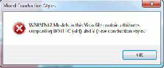
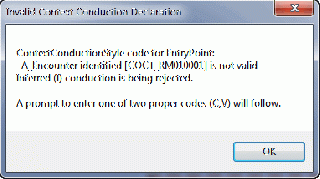
- If the default is x (a conflicted model) display the Warning message shown at in the first (top) figure at right
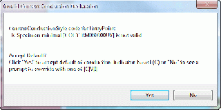
- If the default is "C", "V" or "I" and the Reject Inferred (I) Context Conduction Style option is false, display the Accept Default? message shown in the second dialog box at right.
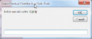
- If the user rejects the default (selects "No" to the previous message), display an "Input box" to enter one of the valid codes, as shown in the third figure at at right. Note that the Input box lists the valid options and will no go away until one of those entries is made. As shown here, it will also allow you to select the default as an answer.
- If the computed default value is "I" and the Reject Inferred (I) Context Conduction Style option is true, then the nominal default is not valid, and the "Accept default" dialog will be replaces by the advisory dialog shown in the fourth position (bottom) at right. If you do not wish to accept either of these, wou will need to accept one of them, remove the designation (subsection below), return the Reject Inferred (I) Context Conduction Style option to false, and re-save the model. At that point, the "I" style will be acceptable.
Changing an Assigned Context Conduction Style Designation
Once a context conduction style has been added to an entry point, the selection process outlined above will not be activated unless the existing style is removed, or becomes invalid. There are two ways to accomplish this:
- For any of the assigned codes, one can edit the Entry Point description (by double-clicking on the box) and then simply delete the property assertion line from the description. When that is done, the next attempt to save the model will activate a new process to assign a valid value.
- If the assigned code is "I", change the Reject Inferred (I) Context Conduction Style option to true, and save the model. This will have invalidated the assignment and allow a different value to be selected. After the change, reset the Reject Inferred (I) Context Conduction Style option to false.
Defining Fixed Sets of Codes For Blocking Context Conduction
In 2010, the HL7 RIM adopted the "vocabulary-based" method of controlling context conduction. In this method, conduction of context defined by Participations or ActRelationship is controlled by two attributes in the ActRelationship class -- blockedContextActRelationshipType and blockedContextParticipationType -- which can be used to block selected types of ActRelationships and Participations, respectively. The two attributes carry the data type DSET<CS>, which permits them to block an arbitrary set of types. These are captured as a Fixed value' of one or more codes from the relevant code system. This section details how to establish such fixed-value sets in the HL7 RMIM Designer in Visio.
Use of Type Code Set to Block Context
The following is taken directly from the UsageNotes for the RIM attributes in question:
- If one or more codes are specified, all other ActRelationships [or Participations] with typeCodes that match one of the specified codes or that are specializations of one of the specified codes will not conduct. All other ActRelationships [or Participations] with typeCodes having a "conductible" property of "true" or whose ancestor has a "conductible" property of "true" will conduct. Conducted ActRelationships [or Participations] behave such that the Act being navigated to is treated as though it had the same association(s) as the Act being navigated from. Refer to the Core Principles specification for more information.
Note: The use of the specialization hierarchy cited above makes it possible to use a single code value to block a set of content. In that circumstance, change the data type from DSET<CS> to just CS and set the code in question as the "fixed" value for that attribute.
Note: in creating an enumerated list (below) it is not necessary to block the children of a blocked code, because they will be blocked by inheritance. Moreover, it is not possible to block just a parent code, without blocking its specializations.
Note: Even if there is a pre-defined Value Set that contains all of the codes to be blocked, this cannot be used in the model design because there is no syntax that can be used to define a fixed value as the set of all codes in a particular value set.
Creating an Enumerated Set of Codes
The following is a detailed set of steps to create an enumerated set of codes as a fixed value, as required for use of these attributes.
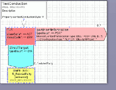
1) Base ModelThe image at right shows the basic model for this exercise. It consists of a single Act that has a "direct" (DIR) Participation that may be set to any of the descendants of DIR, as well. There is a "pertinent information" ActRelationship over which we wish to block conduction of a selected sub-set of the possible "direct" Participations. |
|
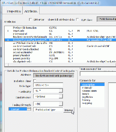
2) Initial Editing of the "blockedContextParticipationType" AttributeThe image at right shows the attributes tab of the RMIM Designers "Clone Editor" with the "pertinentInformation" ActRelationship open. The "blockedContextParticipationType" has been added to the model. To set the first code in the enumeration, select the "Browse" button adjacent to the domain or double-click on the domain name "ParticipationType". |
|
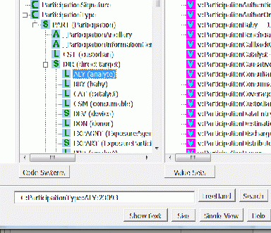
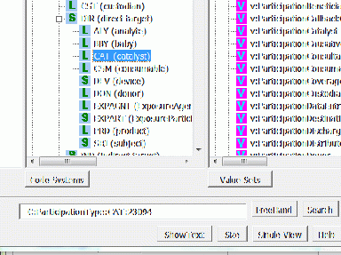
3) Selecting Initial CodeThe previous action will open the Vocabulary Browser preset to look at ParticipationType (as partially seen at right). On the CodeSystems panel, navigate down the Participation hierarchy until you reach the first code to be entered (ALY, in this example), and select "Return" (or press Enter). |
|
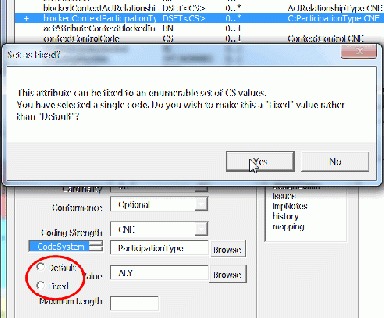
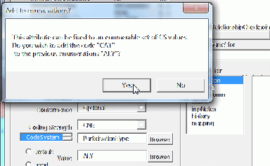
4) Establishing "Fixed" Value for the ResultNormally, when a code is selected, the RMIM Designer will assume that it is intended as a "Default" value. In this case, however, the RMIM Designer uses the data type (DSET<CS>) to trigger an inquiry (seen at right) to determine if you would rather have it assigned as "Fixed." In this case, Click "Yes" or press Enter. Note: There are only three RIM attributes that can have a data type of DSET<CS> (other than those with data type of ANY). They are these two context conduction blocking attributes and InfrastructureRoot.realmCode. In all three the establishment of a fixed enumerated list is a likely requirement. The dialog box seen at right will only ever appear for attributes with this data type. If the dialog at right does not appear, the user should check the "Fixed" value box (circled in the diagram at right). |
|
5) Adding Codes to Make an Enumerated ListTo select another code, double-click on the Fixed value, or click the "Browse" button to the right of that field. This produces the Vocabulary Browser as seen at right. Select the ParticipationType code, within the CodeSystems pane that you wish to add next ("CAT", in this example) and click "Return" or press Enter. |
|
6) Acknowledging Addition to the ListAfter pressing return, the RMIM Designer needs to ask whether this code should be added to the existing list, or used as a new. singular value. As above, the RMIM Designer uses the data type (DSET<CS>) to trigger the inquiry seen at right. The dialog lists both the code to be added and the already-existing list contents. When adding a single code to the list, click "Yes". |
|
7) Extending the ListThe figure at right shows the Clone Editor with a nascent enumerated list. (The brackets are the textual element surrounding an enumerated list.) From this point on, the list can be extended as far as desired by repeating the two preceding steps (5 & 6). |
|
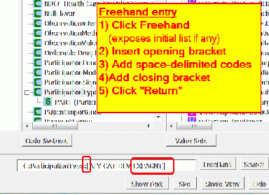
8) Using Freehand Entry to Edit a List or Add Multiple CodesAn alternative to sequential selection (outlined above) is to use Freehand text entry in the Vocabulary Browser. To initiate this, select to "Browse" or double-cick the fixed value entry. In the resulting Vocabulary Browser, click on "FreeHand". This will expose the existing list, and allow you to edit it, as seen at right. If the list is not surrounded by brackets, add these. Then add additional codes using spaces to delimit them. When done, click "Return" or press Enter. Note: This technique can also be used to delete one or more entries from a pre-existing list. |
|
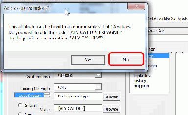
9) Relacing Prior List with Freehand Entry ListThe image at right shows the same dialog box as appeared tree images above, except that this time, both the element to be added and the existing list are enumerated lists. Selecting "Yes" will concatenate these two, which is probably not the desired action. The normal response in this circumstance is to click "No" and save only the list that is coming out of the Vocabulary Browser. |
|
10) Final ModelThe figure at right shows how these lists appear in the final RMIM Designer rendering. In this case, the string: = C:ParticipationType "[ALY CAT DEV EXPAGNT]" represents the fixed enumeration. In the resulting Visio XML file, the attribute element for this attribute will have its own attribute of fixed="[ALY CAT DEV EXPAGNT]" which should propagate through to the MIF representations of the model. |
Updated/Corrected Vocabulary Representations
By February 2011, there were numerous bugs that had been detected and reported on Gforge that were related to the representation of vocabulary constraints in the graphical representations of RMIMs and in the internal displays of the CloneEditor. As part of releases through 4.6.10, the following BUGs were addressed:
- 1840 Command Line Extract of Visio Graphics Crashes after One Drawing - 2011-03-11 16:34:39-07
- 1831 Context Conduction Style Not Always Saved in VSD file - 2011-03-07 12:31:01-07
- 1825 Shape Domain Specification Update Changes Cardinality - 2011-03-04 15:31:03-07
- 1821 Update Class Domain Specs removes 'use exact domain' - 2011-03-03 10:49:55-07
- 1801 HTML Maps are not Valid xhtml - 2011-02-16 07:06:48-07
- 1768 DT ANY will not specialize to DSET - 2011-02-02 15:19:23-07
- 1757 Need to capture context conduction type - 2011-01-25 11:26:52-07
- 1756 Can't pass list of codes - 2011-01-25 11:26:17-07
- 1736 Search Dialog can get pushed behind vocab view - 2010-12-16 21:18:45-07
- [http://gforge.hl7.org/gf/project/visio-rmim-desi/tracker/?action=TrackerItemEdit&tracker_item_id=1840 1090 Default values disappear - 2009-07-09 14:11:00-07
- 1087 Structural attributes display code value as domain - 2009-07-02 13:22:27-07
- 0448 Visio XML Is Not Correct for fixed and default code values - 2008-03-30 01:22:31-07
Of particular note, in this regard, are the following:
- In line with the MnM approved staid model BNF, added a "D:" in front of all concept domain references as they are represented in the graphic display in an RMIM Design. The previous omission of the prefix led to errors down stream because there was not a strong distinction between concept domain and code constraints.
- Corrected error in RMIM Designer CloneEditor that was not correctly interpreting the use of "fixed" value constraints for "non-structural" CS attributes. By previously adopted conventions, the Code System is not included in representation of CS attributes because the code system is expressly bound to the attribute at the RIM level. This representation was correct and consistent as fixed values were saved, but when the class was subsequently loaded in the CloneEditor, the representation was mis-read and later saved incorrectly.
- Corrected dtat-type constraint hierarchy errors that had been reported;
- Corrected behavior of the process of constraining an "ANY" data type to either coded or non-coded specializations; the current implementation displays the correct content in the "Attributes" pane of the Clone Editor as soon as the selection is made, (Previously, these were only updated after saving the class and re-opening it.)
- updated the "Scan and Correct Vocabulary Representations" menu item to adopt the newly implemented representations in any model. This includes the ability to do a batch update and save.
Options to "Scan" and "Repair" Designs
Revamped Shape Updating ... SCAN and REPAIR processes as follows:
- SCAN document - no longer does ANY repair. It simply reports errors.
- REPAIR document - attempts to align all shapes with their correct "Master" Shape and assures GUIDs of masters match the stencil.
- Current process is more thorough than before and more fully repairs drawing anomalies
- Repair and Scan both produce an error scan that can be saved for comparison with prior runs, or for more detailed analysis
Note: This process can be invoked as a "batch" process by using the stencil (RMIM2.vss pane) menu
- MENU:HL7...Batch Conversion/export...Process VSD to HTML Graphics Only (Batch) Then, on the dialog pane that appears, select the following check boxes in order:
- Scan/fix domain specs before export and
- Save Scanned/renamed Visio.
In addition to saving the updated VSD and Visio XML files, this process will create a set of graphic overlay (*.htm) and graphics (*.png) in an Editable sub-directory that is a sibling of the directory in which the selected VSD and Visio XML files are found and saved.
Aligning GUIDs on Shape Masters
Background
The issues that lead to the need to "repair" drawing arise from being multiple "master" shapes of each type -- multiple ActRelationship masters; multiple CMET masters, etc. The repair process involves getting ALL drawing shapes to derive their master properties from the appropriate master shape on RMIM2.vss.
For a number of years, the number of extraneous master shapes was few, and most arose from attempts to copy shapes from one design to another. However, starting in 2007, the number of drawings that needed repair was growing. An in depth analysis in 2010 revealed that the major source of these problems was the process of taking a Visio 2002 drawing, upgrading it to Visio 2003/7 and then reverting it back to 2002. The major factor was that when a Visio 2003/7drawing is "saved as" Visio 2002, Visio assigns NEW GUIDs to all of the Masters! (The process uf upgrading from Visio 2002 to Visio 2003/7 does not cause this to happen.
In part, the way in which the RMIM Designer code was maintained contributed to this. Although most releases were edited in Visio 2002, there were several cases in which code developed in Visio 2003/7 was "saved as" Visio 2002 for distribution. This had the unrecognized and undesirable effect of changing GUIDs on ALL of the masters being distributed.
Further investigation revealed that if one took a drawing file (vsd) or stencil file (vss), saved it using the Visio XML format (vsx or vdx, respectively), the Master GUIDs in this file could be edited (changed) and then the file could be re-converted to binary format. From this arose the basic strategy for aligning master shape guids, that folloes/
Basic Strategy for Aligning Master Shape Guids
- Select a single stencil file that holds the "proper" set of Guids. In February 2011, this is the RMIM2.vss file used with Visio 2003/2007 (and distributed with the tool as RMIM2007.vss).
- Make all changes, particularly to the Visio RMIM Designer code, to this version
- Save this file in XNL (.vsx) format
- Use an XSLT transform to extract a file of the Master Shape Guids. (This file should never change, and has not in the last 15 months)
- Take the file that needs updating (usually a Visio 2002 file that has been created by saving Visio 2007 file "as" Visio 2002 formatr) and save it in XMLformat (.vsx for stencils or .vdx for drawings)
- Apply a transform to this file that takes the Master Shape Guids file as a resource, and changes the Master shape GUIDs of the trarget file to align.
- Load the updated file in Visio and save in binary format (.vss or .vsd.)
Using this strategy a process for managing software releases, and a process for correcting GUIDs in drawing files have been developed, as outlined in the next two sections. Note that the new "combined" Publishing/V3 Generator tool suite includes a "batch" file that will correct the guids in a set of Visio 2002 drawings that have been saved form Visio 2003/7. It automates the three steps of "save as vdx", "run transform to correct", and "resave as vsd."
Steps for Maintaining and Distributing Visio RMIM Designer
- All "programming" will be maintained in Visio 2003-7
- When ready for release, working in Visio 2007:
- Update the release identifier, the RoseTree release dependency and the "change notes" in module "libGlobalConstants" and save RMIM2.vss
- Open RMIM2.vss and load a RIM
- With RMIM2.vss, "SaveAs" a new, compressed Visio RMIM2007.vss file for distribution
- With RMIM2007.vss, "SaveAs" a Visio RMIM2007.vsx file - this becomes the source for GUIDs
- With RMIM2007.vss, "SaveAs" a new, Visio 2002 file as Visio RMIM2002C.vss (C = candidate)
- Working in Visio 2010, load RMIM2007.vss and save with Name RMIM2010.vss. The file format will be the same, but it provides a resource that makes Installing on Visio 2010 easier
- Take these files to a Visio 2002 environment (where installer is created).
- Use RMIM2007.vsx and the transform "Harvest-GUIDsFromRMIM2vsx.xsl" to create RMIM2MasterGuids.xml
- Compare this file with the previous RMIM2MasterGuids.xml file. They should be identical.
- If they are not, the Visio 2003/7 RMIM2.vss file is not a clean descendant of the last distribution.
- This should be corrected by starting with the previously distributed RMIM2007.vss; applying all RMIM Designer code changes to the starter file, and beginning again at step 2.
- Open RMIM2002C.vss in Visio 2002
- Save-as RMIM2002C.vsx
- Apply the transform "CorrectRMIM2002vssGUIDs.xsl" to RMIM2002C.vsx as source and with "RMIM2MasterGuids.xml" as a parameter-linked resource file. Name the result of this transform RMIM2002A.vsx (GUIDs are ALIGNED).
- Open RMIM2002A.vsx in Visio 2002
- Amend libGlobalConstants to reflect the target Visio base environment (Comment out Visio 2007 and uncomment Visio 2002)
- Save as RMIM2002A.vss. Then Re-open
- Export Modules (for SVN synching)
- Save RMIM2002A.vss "as" Visio RMIM2002.vss, which compresses it and prepares the file for distribution
- Place both RMIM2007.vss and RMIM2002.vss in "pending" directory for installation.
- Distribute a SINGLE tool with three VSS files (2010,2007, and 2002). (The logic of the VisioIntall executable has been modified to place the correct file as RMIM2.vss in the "solutions" directory once the target Visio release is known.) Also distribute:
- RMIM2MasterGuids.xml
- Correct2002DrawingGUIDs.xsl
- Harvest-GUIDsFromRMIM2vsx.xsl
- CorrectRMIM2002vssGUIDs.xsl
Steps for Correcting GUIDs in a Set of Visio 2002 Drawing Files
- When Going From Visio 2002 to Visio 2007
- Simply use the Visio 2007 upgrade process. GUIDs remain aligned
- When Going from Visio 2007/2003 to Visio 2002
- In Visio 2007/2003 use the "Revert drawings from Visio 2003..." batch process to create Visio 2002 "vsd" files. (Normally done by the "provider" of the files.)
- In Visio 2002 (usually done by the "recipient" of the files).
- Reference file is RMIM2MasterGuids.xml distributed with this package
- Open Visio with a blank RMIM2 drawing. Use the Batch process from the HL7 menu when the stencil is selected and find "Convert ... VSD ... to VDX..." to make one VDX file for each VSD file that you received.
- Run the "Correct2002DrawingGUIDs.xsl" transform with the "visMasterGUIDs" parameter pointing to the RMIM2MasterGuids.xml file distributed, and the source file(s) being the "*.vdx" files created in the preceding sub-step and save the result "over-writing" the source.
- Open Visio with a blank RMIM2 drawing. Use the Batch process from the HL7 menu when the stencil is selected and find "Convert ... VDX ... to VSS..." to make one VSD file for each corrected VDX file from 2-b-iii. (Can overwrite.)
- These are your working "GUID-aligned" files for use in Visio 2002.
- When ready to send them back to the "provider" simply wrap the changed VSD files and send them.
Dual Data Sources and Deferred Vocabulary Assembly
In mid-June 2011, RoseTree was modified in two ways:
- To allow the configuration data for RIM and Vocabulary content to be loaded solely from MIF files.
- To "defer" the assembly of vocabulary concept data from the vocabulary MIF file until the user or program acquired the data.
RMIM Designer release 4.7.5 was modified to take advantage of and adapt to these changes. The specifics of these changes do not appear here. Rather, they are represented in updates to the following, previously published, sections of this documentation:
- The Model Selector dialog used to select source configuration files for the RMIM designer
- The Command Line syntax for specifying configuration files, where the change is limited to expanding the "type" of files that may be declared for the source "database".
- The Vocabulary Search dialog used in the Vocabulary Browser.
The June 2011 changes had no effect on any other function or display within the RMIM Designer.
