RMIM Diagram Representation
Contents
Introduction
This page is intended to capture discussion and considerations related to whether the next generation of the Static Model Designer needs to retain support for the "traditional" HL7 static model diagramming syntax, and if so, what sort of support is necessary.
Background
HL7 (Visio) Diagrammatic Representation
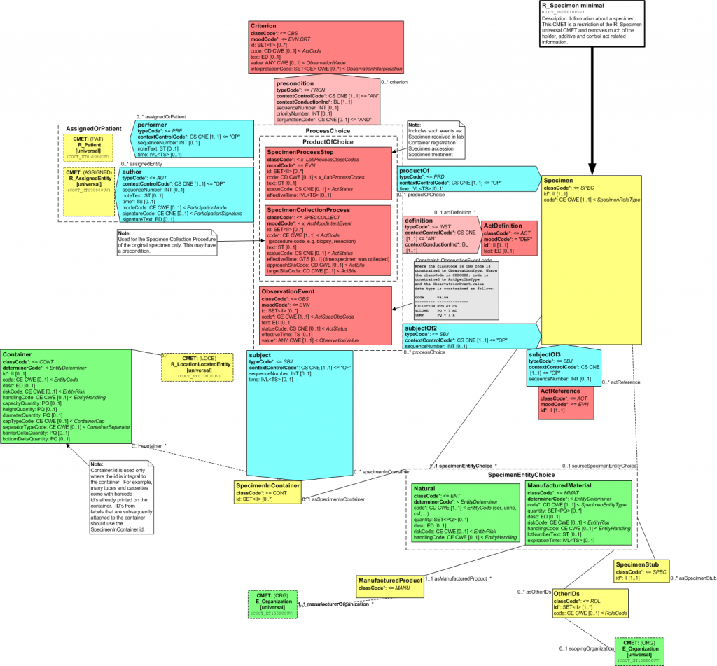
HL7 has had a specialized diagrammatic representation used to render static models such as DMIMs (DIMs) and R-MIMs (CIMs). This representation includes: - arrow-shaped boxes and "recursive corner" boxes for relationship classes. - surrounding dashed-line "boxes" to designate choices - a box with an out-going arrow to designate entry points - specialized shapes to designate CMETs and shadows - special boxes to represent subject areas and subject-area references - distinct shapes for comments and constraints - color-coding to reflect RIM derivations - additional attribute and association characteristics including isMandatory, conformance, default and fixed values, business names, vocabulary bindings, update mode, etc. The "standard" UML syntax uses none of these conventions and does not expose some of this information
OHT - NHS sponsored Static Model Designer Diagrammatic Representation
The next generation of the static model designer developed by the NHS currently uses underlying Eclipse graphical design features that do not support the HL7 specialized diagramming syntax. Some elements are or will be supported. Some are not yet supported. Some are not planned to be supported, at least in the "design" view. There's the possibility of using automated layout to generate a v3 view, but this possibility is likely to be technically challenging and does not have a high probability.
Standard UML Diagram Notation
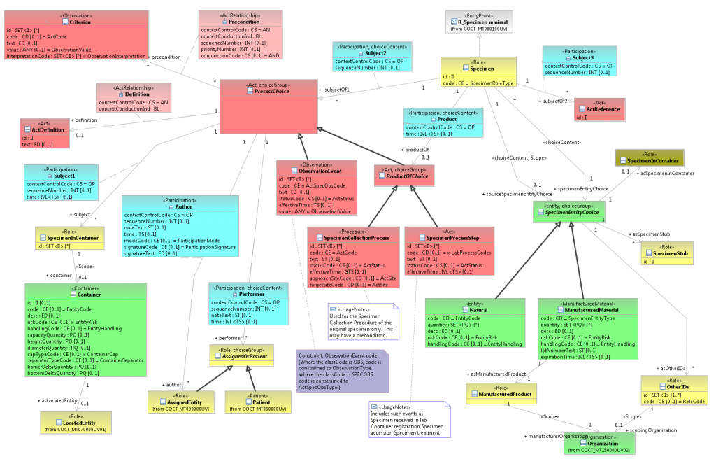
UML class diagram notation is a widely adopted standard that is taught in most universities and is understood by most implementers of HL7 standards. A well-defined relationship to UML standard notation would help promote adoption by the HL7 user community. If UML class diagram notation is used as the baseline for HL7, then the unique HL7 extensions may be specified as optional or recommended notational decorators. Some UML tools may then include an alternative class diagram view using these HL7 decorator extensions. The primary difference is in displaying additional attribute metadata and choice groups. HL7 extended metadata is retained in UML stereotypes and is viewable in property view editors. The choice group representation in UML is nearly identical to that in MIF (choice items as class specializations). The standard UML class diagram, as shown below, displays the choice group content as represented in MIF.
Sample Traditional diagram (Visio)
Following is a reduced image (click to enlarge) for R_Specimen Universal. The full definition for this CMET can be found in the current HL7 Ballot.

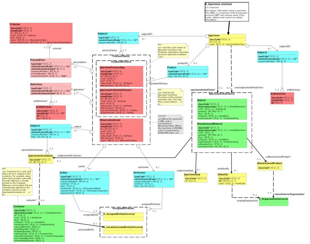
New SMD diagram (Eclipse)
The semantic concepts are expressed as follows:
- Attributes
Same as before, properties such as mandatory, fixed/default values, conformance, datatype and vocab info displayed as before.
- Entry point
Same as before, except non-orthogonal connection is also supported
- Classes
Color coded based on archetype. Naming is supported according to the HL7 formal naming algorithm. All classes are box shaped. The Visio style arrow shaped boxes are represented as a class with two associations, therefore can be connected in any angle.
- Associations
Player, scoper and regular associations are the same as for the Visio style diagramming. Formal naming is supported. In addition traversability is also indicated on the associations. Recursive connections are simply pointing back to the source class. Directionality is maintained, for example directionality of ActRelationships (what's a subject of what) is immediately visible.
- Choices
Same as before in the Visio style designer. Choice within choice is supported.
- Annotations
Annotations are supported, note and constraints are displayed as "sticky notes" in different colors.
- CMETs
Will be supported in the second phase of the project.
- Templates
Will be supported in the second phase of the project.
- Note: CMETs are not supported by the current version of the SMD, they were substituted with classes in the above diagram.
For more screenshots, please click here.
Comments
Grahame
- Looks pretty good actually. 2 comments: what's with the html control elements? And with regard to space, does it have to laid out with so much space? Can't we diagram with the same density as the existing diagrams? --Grahamegrieve 11:23, 16 January 2009 (UTC)
- 1. Currently, the annotations within the diagram are handled as plain strings. However, these annotations are edited using a rich text editor as html (formatting buttons, etc..). As for the spacing, the user can lay-out or rearrange these artefacts in a more compact fashion if needed. Bbanfai
- 2. The default layout comes as out of box functionality and we are trying alternate layout's that can reduce the space efficiently in the second phase.Ravi Natarajan
Rene
- Personally I don't have a problem with this visualization of the model. Anybody with any background in modelling should be able to grasp what this is trying to convey. It would be nice to have a side by side rendering of one and the same model (a densely-packed class-rich model, with its layout optimized -in both tools- by a human designer) to see if the "space" requirements are an issue. I guess it doesn't have to be an issue if the layout is optimized (as it is Visio) by a human being. Rene spronk
- That's the same conclusion we reached on the MnM call last week. We'll create a version of COCT_RM080100UV with the new tool to allow easier comparison. --brandonulrich 13:33, 5 February 2009 (UTC)
Rik
- Agree that this looks good. On the cosmetics, the choice of thick black lines for scopedBy/PlayedBy and choice boxes makes them stand out more than the light grey ones. Your eyes are drawn to the choices and entity relationships, which are often not the key elements.
- Perhaps the light grey needs to be a darker shade, or the black and grey reversed.
- Suggest the choice box dotted lines are changed to a different shorter dot length that the scoped by, to show that these are not related.
- The circular end points of the lines has the effect of blurring where the line actually connects in some cases. For instance on the productOfChoice, you can't immediately see which choice box this connects to. What do these circles represent? The S and T is source and target presumably. Visio supports the arrow being "backwards", changing the sense of the relationship, and the cardinality (traversability, serialization) being on either end, or both ends, in a DMIM. It would be good to see how these options are represented. -Riksmithies 13 Feb 2009
- The circular end points indeed represent source and target, the arrows on the association ends represent the traversability of the given end. The SMD supports all four permutations:
- Traversable + Source = S + arrow
- Traversable + Target = T + arrow
- Non-traversable + Source = S
- Non-traversable + Target = T (Zsolt Török 13 Feb 2009)
- The circular end points indeed represent source and target, the arrows on the association ends represent the traversability of the given end. The SMD supports all four permutations:
Lloyd
(From tooling list email)
- A few questions/suggestions for the SMD representation:
- Can we make CMETs have a small dashed border? It would just call them out a bit more and make it more obvious that they aren't regular classes.
- Can we make the "S" and "T" designating source and target for arrow classes black and bold so they jump out a bit more? (Fine if the circle and arrows are still grey.) Also, the letter isn't always rendering properly in the center of the circle which can make it a little hard to read.
- The constraint specified in your sample isn't the same as the one above and is missing the identification of the attribute it deals with
- The notes (& constraints) should ideally render the XML markup rather than exposing the raw XML
- Any particular reason for making the notes yellow instead of white? --Lloyd on Tooling list
Mike B
(From tooling)
- Can we make sure that each class is NOT only represented by color. Could we have the base class listed in the box somewhere? (like the UML model) Or maybe an abbreviation like 'A' for Act, 'AR' for ActRelationship, 'R' for Role etc.
Speaking from experience, color blind people have trouble with some of these colors. This fix would also help the diagrams to conform to the Section 508 guidlines put out by the US gov't.
Brandon
In response to some of the comments:
- It's easy to change the line styles (color, intensity, dash length) and cosmetic issues, as long as a consensus emerges on how they should be represented.
- We're not entirely convinced of the S and T for source and target either; open to better ideas. We thought about hollow and solid figures (circles, aggregation/composition diamonds) as well. We just want to be careful not to visually confuse source/target with traversable/nontraversable.
- Constraints have both visual and machine-processable data, respectively expressed as XHTML and OCL. Not sure of the utility and/or return on embedding a browser in a sticky note, but could be done...or perhaps the OCL could be exposed instead. The OCL is used by the validation framework.
Standard UML diagram (same model)
Following is a reduced image (click to enlarge) showing standard UML notation for the R_Specimen Universal CMET. Software developed in the Open Health Tools (OHT) Modeling Tools for Healthcare project was used to import the MIF2 representation of this CMET into UML.
The proposed SMD diagram notation is very similar to standard UML notation. It may be beneficial to define HL7 diagram notation as optional notational extensions for UML tool vendors. The notational extensions are guided by use of UML profile stereotypes that capture additional HL7 metadata.
Profile stereotype documentation for HL7 extensions will be added to the OHT modeling tools project wiki. A hyperlink will be added to this page when it is available.
The salient characteristics of using standard UML class diagrams for HL7 are as follows:
- Class: The RIM derivation is displayed using both stereotype and color. Most UML tools support choice of class background color. The OHT modeling tools project has automated the assignment of HL7 color based on the RIM derivation of classes.
- Shadow Class: The diagram convention of HL7 "shadow classes" is supported by hiding attribute and operation compartments and making the class background color a darker shade. See the example of SpecimenInContainer in the diagram shown above.
- Structured Attributues: The HL7 structured attributes (classCode, typeCode, moodCode, and determinerCode) are represented using properties of the RIM stereotype on each class. The values are editable via property view fields. The idea behind this design is that many structured attribute values are predictable by users based on the RIM derivation, and the diagram is less cluttered if those attributes are not shown for every class in the diagram. For example, most Observation classes have classCode=OBS and moodCode=EVN.
- CMET: CMET class references are displayed using a class box with attribute and operation compartments hidden. The CMET package name is shown within the class box using UML parent name of the class, e.g. (from COCT_MT090000UV).
- Choice Group: Choice group members are displayed using UML generalizations, which is how they are represented in the MIF. UML tools support user assigned changes to line weight and color, but relationships may not be changed to dashed lines because this has special significance in UML notation. In this example, the line weight of generalizations was increased to make choice groups more obvious.
- Association Class: The HL7 types for Participation, ActRelationship, and RoleLink are represented in UML using an Association Class. We discussed this in detail during the UML BOF at the Sept 2007 WGM, and the consensus was that association classes are a good match to the original intent of these types in HL7 methodology. When transforming MIF to UML models, the two separate associations are collapsed to one association, and all attributes are fully modeled in the association class. The use of two separate associations seems to be more of an implementation design view than a conceptual modeling view.
- Association: Scoper associations are represented and displayed in UML diagrams with the <<scope>> stereotype. We are investigating the UML representation and diagram notation for source/target of association ends (see discussion in SMD diagram section).
- Annotations: All HL7 model annotations are represented and (optionally) displayed on diagrams as UML comments. The various kinds of annotations are distinguished using stereotypes, e.g. <<Definition>>, <<Design>>, <<UsageNotes>>, etc. Any UML model element may have zero or more comments.
- Constraints: Model constraints are represented and displayed using UML Constraint. This is a separate metaclass from Comment. Each UML constraint specifies its language (e.g. "analysis" or "OCL") and the constraint text. Any UML model element may have zero or more constraints.
Pros and cons
Benefits of the 'traditional' syntax
- Extremely space-efficient. Diagrams can be fit on a page or two with little white-space and lots of information
- "Important shapes" like Act, Entity and Role stand out more than Act-Relationship, Participation and RoleLink
- Directionality of ActRelationships (what's a subject of what) is immediately visible
- Names of relationship classes (e.g. Subject2, Subject3, Subject 24) that don't appear in the instances don't clutter up the diagram and annoy people
- Choices focus on the concrete classes, not the irrelevant abstract ancestors
- Serialization mechanism made clear through presence or absence of cardinality
- Significant HL7 familiarity with syntax
- Significant migration effort
- All existing published and balloted static models use the old syntax and would require conversion to move
- All of our existing documentation (e.g. V3 Primer), presentations, etc. use the old syntax
Benefits of the new Eclipse SMD syntax
- This is a modeling tool, therefore the diagram is model 'aware'. For example it does not allow different archetypes to be added to a Choice.
- Better supported by Eclipse technologies
- Classes can be connected in any angle, more compact models, therefore no shadow classes are necessary
- Auto-layout algorithms can be applied
- Arrow shaped classes are displayed as they really are: a class with two associations. Directionality of ActRelationships (what's a subject of what) is immediately visible.
- More familiar to the non-HL7-initiated, in particular implementers
Benefits of the 'straight' UML syntax
Note: If UML is used for designing HL7 (RIM) conformant information models,
the users will require a UML profile (e.g. HDF UML Profile) to support HL7-specific extensions.
- Eclipse structure supports it out-of-the box
- Supporting the HL7 custom syntax would require substantial customization
- Increased cost, risk of bugs - [Where is the increased cost coming from? Vendors are offering free UML tools to HL7.]
- Ability to take advantage of new features added by Eclipse over time
- More familiar to the non-HL7-initiated, in particular implementers
- Helps better expose content from a UML modeling perspective
Additional Considerations
- MIF supports capturing multiple graphical renderings of a single model. Specifically, it can support both standard UML and traditional HL7 diagrams for a single model
- MIF does not support this, the tools support this. One could also implement a custom diagram editor for the UML language that displays HL7 preferred diagram notation. Dave Carlson
- If we support multiple renderings and don't have auto-layout, committees would need to edit layouts in both styles that would mean increased work
- If we go with an auto-layout route, it's probably easier to do auto-layout of traditional UML than non-traditional, seeing as it's not space-efficient anyhow and the odds of off-the-shelf auto-layout software for standard UML is much higher than for the HL7-specific syntax
Other Discussion
We could use Eclipse-based UML 2.1 tools with HL7-specific extensions
- The UML diagram would look very similar if we used appropriate UML extensions (aka UML profiles). The following diagram shows the use of UML 2.1 and HL7-specific profile (based on the HDF Profile draft)
- Please note that a stereotyped "generalization" association is used to specify the classes that are members of a choice
Sample UML-based diagram for POCG MT000040UV: Family History (May 2008 Ballot)
HL7 members have access to free UML tools
- The cost of using UML to create static model diagram is free for HL7 members as follows:
- The OHT Modeling project provides a free Eclipse plugin that contains all the extensions required to author HL7 models in UML
- IBM and other vendors provide free Eclipse-based UML 2.1 tools. This program would be available to other SDOs or not-for-profit organizations that produce standards HL7 would like to harmonize.
Resolution
We will discuss this on the January 30th conference call


